Programming With RoboLogix
RoboLogix uses a Scripting-type programming language in order to control the software application and it utilizes a command, or instruction set, that is common among major robot manufacturers. Like most robot programming languages, RoboLogix programs consist of Data objects and Program flow. The data objects reside in Registers and the program flow represents the list of instructions, or instruction set, that is used to program the robot.
Programming languages are generally designed for building Data structures and algorithms from scratch, while scripting languages are intended more for connecting, or gluing, components and instructions together. Consequently, the RoboLogix instruction set is a streamlined list of program commands that are used to simplify the programming process and provide rapid application development.
An important consideration when writing programs in any language is to have good Documentation to accompany the lines of Code that have been created. This makes the process of manually interpreting the program code much easier for modification, adjustment, and understanding the program operation. With RoboLogix, the documentation feature is provided by Comment Lines, which can accompany every line of code that is written. When writing comments for documentation purposes, it is important to be as brief, but concise as possible. Usually only a few words or a short sentence is all that is needed to describe a particular programmed instruction. For example, the comment to accompany C1_ON could be something as simple as “Energize packaging conveyor”. Comments can also be attached to program names, registers, and any instruction contained in the instruction set.
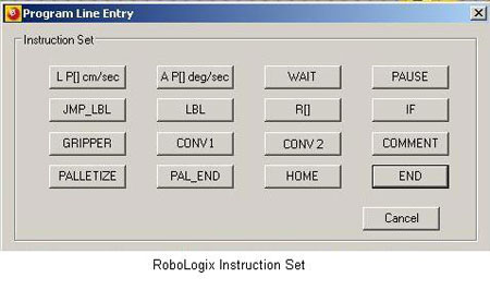
The RoboLogix instruction set contains 16 commands, which are usually written as a program on a line-by-line basis. These commands are used to instruct the robot to perform tasks such as moving to a specific location, picking up an object, executing a Subroutine, waiting, etc.
One of the more popular commands in the instruction set is the IF instruction, which compares numerical values located in two registers. If a register has a value that is greater than (>), less than (<), greater than/equal to (>=), less than/equal to (<=), equal to (=), or not equal to (<>) another register, it will execute the next line in the program if the condition is true. The IF command is often used with the JMP LBL instruction to control program execution.
All instruction set information is stored in registers, which are data locations capable of holding variable numeric values. The difference between the display of Registers and Instructions is that Registers use square-brackets “[ ]” to indicate a Register address. For example, Register number 1 would be written in RoboLogix as R[1}. Instructions are always indicated in capital letters (i.e. IF, WAIT, etc.) and may use an underscore “-“ to indicate an address or identity.
There are three main types of registers used by RoboLogix: Position registers, palletizing registers, and variable registers. Position Registers contain linear and angular data point coordinates and include axis (joint) information for A1, A2, A3, etc. and for X, Y, Z linear coordinates. The 32 Palletizing Registers are capable of storing 16 unique palletizing configurations. There are also 32 Variable registers which can be used for holding instruction set data such as position comparisons.
Any data in any location, including program lines and registers, are selected by left-clicking on the numbered grey buttons on either the left side or at the top of the display screen. Once selected, a red highlight bar appears that allows data to be deleted or loaded for editing. To edit the contents of any register, it must first be highlighted and once the register has been highlighted, its value can be changed by entering a new value in the dialog box.
Each command contained in the instruction set is either angular or linear and consists of a feederate override, which represents a percentage of linear, or circular feedrate. As mentioned earlier, Feedrate override is an instruction that controls the programmed feedrate by an adjustable percentage during operation. The Setup key provides access to the system setup dialog box, shown below, with setting adjustments for feedrates for angular (Deg/Sec.) and linear (cm/Sec) jog and conveyor instructions.
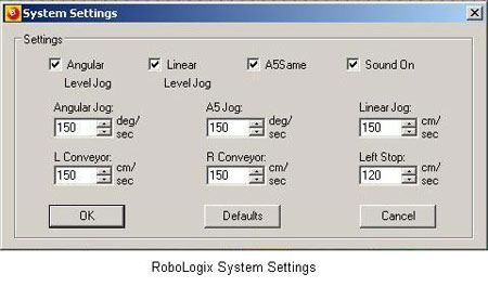
The following system control settings are accessed through the system setup dialog box:
Angular Level Jog |
Maintains workpiece in a level position while being jogged. X-Y and Z-Y orientation is held constant. |
Linear Level Jog |
Maintains workpiece in a level position while being jogged in a linear motion. X-Y and Z-Y orientation is held constant. |
A5 Same |
Maintains attitude in X-Z plane. |
Sound On |
Audio control (sound effects) |
Angular Jog |
Changes default maximum feedrate in deg/sec, which can be fractionally adjusted at 5% intervals using feedrate override buttons on main screen. |
Linear Jog |
Adjusts default maximum feedrate in cm/sec. |
A5 Jog |
Adjusts A5 axis rotation speed in deg/sec. |
L Conveyor |
Adjusts speed of Conveyor 1 in cm/sec increments. |
R Conveyor |
Adjusts speed of Conveyor 2 in cm/sec. |
Left Stop |
Workpiece limit switch position. Indicates location on Conveyor 1 where workpiece will stop. |
The RoboLogix programming console, or control panel, consists of five separate display screens: main display screen, programming screen, position register screen, variable register screen, and INFO screen. While RoboLogix is a proprietary robot programming language, the various commands, registers, display screens and overall program design and layout is intended to closely replicate the most common features found in modern industrial robots by companies such as Fanuc, Kawasaki, etc.
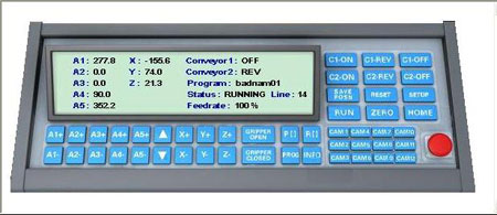
The Main Screen display indicates angular joint positions (A1 – A5), and the Cartesian positional coordinates (X,Y,Z). In addition, the Main Screen also displays status information for the conveyors and any other Ancillary control devices that may be used in the work envelope. Program information such as program name, status (run, wait, etc.), and program line count, is also displayed on the Main Screen.
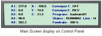
The Main Screen also displays active state information for the conveyors and any other ancillary control devices that may be used in the work envelope. Program information such as program name, status, program line count and feedrate is also displayed on the Main Screen. The feedrate adjusts the operating “speed” of the robot and can be altered by the vertical arrows located between A5 and X on the control panel. The feedrate can be varied in 5 degree intervals.
The Status line displays conditions such as LOADED, WAITING, RUNNING, Ended, ESTOP, and RESET. When the Status line indicates LOADED, it means that the program has been loaded and is ready to run. The WAIT status indicates that the program is waiting a pre-determined amount of time before it continues to execute. When the Status is shown as RUNNING, it means that the program is executing. ESTOP is only displayed when the red emergency stop button has been pressed. When the Status indicates RESET, it means that the RESET button has been pressed on the control panel. The RESET command is used to clear faults, such as a damaged workpiece and to reset the program back to its original starting point.
In addition to the default Main Screen displayed on the Control Panel, there are four additional screens that are displayed when programming with RoboLogix. One of these screens is for displaying position registers, variable registers, text-based messages, and the actual program code. The Control Panel has four buttons to access the position register screen (PRS), the variable register screen (VRS), the programming screen (PRG), and the text information screen (INFO).
The Position Register Screen (PRS) displays all assigned program positions. Each program written with RoboLogix can hold up to 10 position registers, P[1] – P[10], with each position register containing joint position and X, Y, Z coordinate data. Position register data can be altered (edited) by clicking on the position register heading, i.e. P[1], which will launch a dialog box for editing numeric data. The dialog box will also display all assigned labels, or comments. Each position register has a Comment function which allows for the entry of text “comments” regarding a device, program segment, or reference in the program.
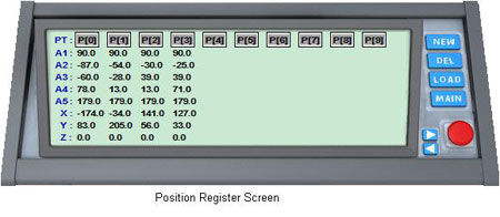
The buttons located on the right side of the PRS are labeled New, Del, Load, and Main. The New instruction assigns a position register to a new position. Specification of position can be done manually or by the SAVE POSN button on the Home Screen. The DEL command will erase contents of a selected position register. The LOAD instruction loads the position register data into the dialog box for editing. The Main buttons returns the control panel to the main, or home screen.
To store a position in a position register, the SAVE POSN button is pressed on the main control panel. This button basically takes a “snapshot” of the robot’s angular and linear coordinates and stores them in the next available position register. For example, if you create a new program, the position registers are initially empty. When you move the robot to the desired position and click the SAVE POSN button on the control panel the position data will be automatically stored in register P[0], the next saved position will be in P[1], and so on. It should be noted that for RoboLogix, and most major robot manufacturers, fine position adjustments are made more accurately using X, Y, Z adjustments instead of A1 – A5 angular adjustments.
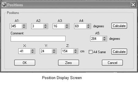
To edit a stored position select the desired position point to be modified by left-clicking on the position (i.e. P0, P1, P2, etc) so that a red vertical highlight bar appears. Click on the Load button to load the position data and a position display screen should now appear. Note the two Calculate buttons on this display screen. These buttons are very important since whenever you alter the A1 – A5 position points or the X, Y, Z position points, you must press the corresponding Calculate button in order to make the proportional change between the angular and linear position points. For example, if you change the X, Y, Z parameters you must press the Calculate button located to the right of the X, Y, Z numeric displays.
A useful feature when editing position points is to be able to move the robot to the position being edited. This allows you to obtain a visual correlation between the numerical values of each axis, and the actual position of the robot. To view a position point in the Position Register Screen, select a register and click on the top arrow key located beside the emergency stop button on the control panel. The upper arrow key will advance the register by one position, and the lower arrow key allows you to move back one register. With these arrow keys, you are able to step the program in both a forward and backward direction to “walk” the program through its various programmed position points.
The Variable Register screen (VRS) displays 32 registers (R0 – R31) which contain numeric variables. These variables can be assigned for holding data such as instruction set command information. For example, if a WAIT command was to be used with a value of 10 seconds, the WAIT instruction would contain a reference to a register, i.e. R[1] and the register would hold the number 10.
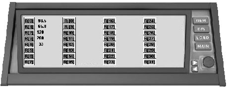
Variable registers are used to store numeric information such as data for counters. The most common application for counters in robot programs is for counting loops. A loop is a repeated execution of a section of a program. By counting loops, you can control the number of times that a program is executed. For example, if you wish to stack five boxes, you would write a program to count five loops of a box-stacking routine and store the count data (5) in a variable register (i.e. R[1]).
Loops can be created by inserting a LBL instruction at the beginning of the program you wish to loop, and a JMP LBL command at the end. An LBL instruction is an unconditional branch which allows you to loop part, or all, of a program. The LBL and JMP LBL must have the same reference address in order to function. The following program code is an example of a loop routine:
1. LBL [1]
2. AP[0]
3. WAIT 1
4. LP[1]
5. AP[2]
6. GRIPPER Close
7. AP[3]
8. GRIPPER Open
9. JMP LBL [1]
The Programming Screen (PRG) is the display screen where RoboLogix programs are entered, edited, saved, and retrieved. Each line of program code can be edited, by clicking on the line to launch a dialog box with various edit functions. A new line of code can be started by using the New instruction, which will add a new line immediately below the last line. The Programming Screen displays up to 7 lines of code at a time. When a program is longer than 7 lines, subsequent lines of code would be displayed on the next program screen which is accessed by the right arrow key located beside the emergency stop button.
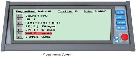
Programs that have been previously written and stored can be retrieved from system memory by pressing the Load button on the Programming Screen. This instruction will launch a dialog box which will allow you to search for a program on the system’s hard-disk or ancillary memory device. When there are large numbers of programs stored in memory, they can be browsed by using the arrow keys located beside the red emergency stop button on the Programming Screen. The right arrow key allows you to view the next 7 program names stored in memory and the left arrow key provides access to the previous 7 program names.
The INFO button accesses a program description display screen, which can contain a short descriptive summary up to 400 characters in length. The program description display screen is shown below, and is the default display screen for any of the pre-built lab projects that are included with RoboLogix.
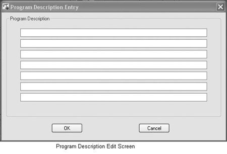
Program descriptions are useful when designing your own programs since it allows you to write and store additional documentation to accompany your program. The New and Load keys on the program description display screen allow you to write a new description or edit an existing description.
Programs that have been previously written and stored can be retrieved from system memory by pressing the Load button on the Programming Screen. This instruction will launch a dialog box which will allow you to search for a program on the system’s hard-disk or ancillary memory device. When there are large numbers of programs stored in memory, they can be browsed by using the arrow keys located beside the red emergency stop button on the Programming Screen. The right arrow key allows you to view the next 7 program names stored in memory and the left arrow key provides access to the previous 7 program names.
Once a program has been loaded, it can be launched, or executed, by using the Run function. When the Load button is pressed in the programming mode, it loads the selected program, and a dialog box appears called “Program Name Entry” which allows you to change the program name or comment. When a program is running, the Program Display Screen will show a red highlight bar. This highlight bar indicates which program line is being executed, and moves sequentially from one program line to the next.
Whenever a program is created or modified, it is automatically saved. Any change that is made to any program variable is saved automatically. The autosave feature is activated when you change from one display screen to another or when you exit the program.
When creating, or writing, a new program, the Create New Program dialog box appears when you press the NEW key on the program display. The Create New Program dialog box allows you to enter the name of the new program as well as a descriptive comment. In addition, this dialog box also has a setting called Rename which allows you to make copies of the program. For example, if you wish to make a copy of program “PAL1”, select the program by pressing the PROG key and loading the program. Once the program is loaded, press the NEW key, select Rename in the dialog box and change the name of the program (i.e. PAL2). By clicking “OK” you have now created a new program (PAL2) which is identical to the original program (PAL1).
When you load an existing program, a Load Program Dialog box appears which has a Program Only setting to allow you to load only the program lines of code, but not the program’s variable registers, position points, conveyor speeds, etc. The Program Only feature allows you to load a new program while retaining all of the control data and position information from another program. It is useful in applications such as palletizing, where you can write one program to palletize workpieces in a certain configuration, and write a second program to de-palletize without changing the configuration.
As with any programming language, there are many “rules of thumb” that are useful when writing programs using RoboLogix. Some of these recommendations for writing lines of code include:
- Lines of code should be less than 50 characters in length and be limited to one statement per line.
- Restrict each program to a maximum of 20 lines of code. Programs larger than 20 lines should be broken into sub-programs.
- When naming procedures in a program, indicate action by using verbs, and use names for functions that return values.
- Use comments to explain why and what is being performed in the program, rather than how it is being performed.
One of the most important rules of thumb for robot programs using a gripper is to be as accurate as possible with gripper position points. In order to pick up a workpiece (box) using RoboLogix, the gripper must be precisely positioned for the gripper to effectively close and pick up the box. Precise alignment requires that the gripper’s fingers are located at the center of the box and that the fingers are extended almost to the bottom of the box.